


Brief
Tutorial: Use the STM32 development board and STONE LCD screen to develop beauty devices with touch screens

Figure 1
Because I have a lot of contacts with ST, MCU like this type can generally plug in the screen through IIC or SPI or serial port, such as 0.96-inch display screen, 1602 LCD screen, and various TFT LCD screens, and I decided to use the STONE LCD screen to do this project. Speaking of the STM32 board.
Project requirements
Here we want to do a project about the use of medical devices and instruments. This project is mainly through our STVC101WT-01 serial port screen, through the touch mode. After pressing the key, the serial port screen sends the serial port command to STM32l053r8 through the serial port command. When our STM MCU receives the specific command, it starts to analyze the command, This resolution protocol is specific, which will be discussed later. After that, MCU will analyze and recognize specific fan instructions and led instructions, so as to realize the control of fan and led.
There are four functions
Serial port screen realizes touch key function
Send touch command
MCU analyzing instruction
Control the FAN and LED
After the function is determined, we need to select the model of each module:
Type of touch screen
What kind of MCU module do we use
What kind of peripheral module to use
I plan to use STVC101WT-01 serial port screen for touch screen, after all, it is very convenient to use, and the market also has a certain proportion, the most important thing is that it is easy to use; the problem of the screen is solved, and then an MCU should be selected. Why do I use STM32l053r8 for MCU? Because the global market share of St MCU is more than 11% in 2015;
We use a 5V 4W DC power supply for the fan so that it can be controlled directly through the IO port; an ordinary LED is used.
Introduction and principle of each hardware
Fan
Generally speaking, fans have fan blades, which are electric-driven devices to generate current. The fans configured in the fans are powered and then turned into the natural wind to achieve the cool effects.
Structure
Rotor: it is composed of the magnet, fan blade, and shaft; stator: it is composed of silicon steel sheet, coil, and bearing; control circuit: it is composed of IC induction magnet N.S. pole to control its coil conduction through the circuit and generate internal excitation to make the rotor rotate. Type: an axial fan, DC fan. Size: 40mm * 40mm * 15mm.

Figure 2
Working principle
The main components of the electric fan are the DC motor. Its working principle is: the electrified coil rotates under the force in the magnetic field. The transformation form of energy is: electrical energy is mainly converted into mechanical energy, and because the coil has resistance, it is inevitable that part of electrical energy will be converted into thermal energy.

Figure 3
LED
LED. It is made of compounds containing gallium (GA), arsenic (as), phosphorus (P), nitrogen (N), it can radiate visible light when electrons are combined with holes, so it can be used to make light-emitting diodes. In circuits and instruments as indicator lights, or composition of text or digital display.
Characteristics of LED
It uses the solid semiconductor chip as the light-emitting material. Compared with traditional lamps, LED lamps have the advantages of energy-saving, environmental protection, color rendering, and response speed. It has the following characteristics:
① Energy saving is the most prominent feature of LED lamps. In terms of energy consumption, the energy consumption of LED lamps is one-tenth of that of incandescent lamps and one-quarter of that of energy-saving lamps. This is one of the biggest characteristics of LED lights. Now people are advocating energy-saving and environmental protection, and it is precise because of this feature of energy-saving that the application of LED lamps is very wide, It makes LED lamps very popular.
② It can work in the high-speed switch state. When we walk on the road, we will find that every LED screen or picture is unpredictable. This shows that the LED lamp can work at high speed. However, for the incandescent lamps we usually use, we can not achieve such a working state. In normal life, if you switch too many times, it will directly lead to filament breakage. This is also an important reason for the popularity of LED lights.
Principle of LED
The LED has single guide electricity. When a positive voltage is applied to the LED, the holes injected from the P-region to the N-region and the electrons injected from the N-region to the P-region are combined with the electrons in the N-region and the holes in the P-region within a few microns near the PN junction, respectively, to produce spontaneous emission fluorescence. The energy states of electrons and holes are different in different semiconductor materials. When electrons and holes compound, the amount of energy released is different. The more energy released, the shorter the wavelength of light.

Figure 4
Describe of STVC101WT-01
10.1 inch 1024×600 industrial grade TFT panel and 4-wire resistance touch screen;
brightness is 300cd / m2, LED backlight;
The RGB color is 65K;
visual area is 222.7mm * 125.3mm;
visual angle is 70 / 70 / 50 / 60;
working life is 20000 hours. 32-bit cortex-m4 200Hz CPU;
CPLD epm240 TFT-LCD controller;
128MB (or 1GB) flash memory;
USB port (U disk) download;
toolbox software for GUI design, simple and powerful hex instructions.
Basic functions
touch screen control / display image / display text / display curve / read and write data / play video and audio. It is suitable for various industries.
UART interface is RS232 / RS485 / TTL;
voltage is 6v-35v;
power consumption is 3.0w;
working temperature is – 20 ℃ / + 70 ℃;
air humidity is 60 ℃ 90%.
STVC101WT-01 module communicates with MCU through a serial port, which needs to be used in this project. We only need to add the designed UI picture through the upper computer through the menu bar options to buttons, text boxes, background pictures, and page logic, then generate the configuration file, and finally download it to the display screen to run.
in addition to the data manual, there are user manuals, common development TOOLBox, drivers, some simple routine demos, video tutorials, and some for testing projects.
STM32L0538
The ultra-low-power STM32l053x6 / 8 microcontroller combines the connection capability of the universal serial bus (USB 2.0-less crystal) with the high-performance arm ® cortex ® – M0 + 32-bit RISC core running at 32 MHz.
STM32l053x6 / 8 device has many analog functions, one 12 bit ADC, one DAC, two ultra-low-power comparators, multiple timers, one low power timer (LPTIM), three general 16-bit timers, one basic timer, one RTC, and one stick can be used as a time base. They also have two watchdogs, a watchdog with independent clock and window functions, and a window watchdog based on the bus clock.
In addition, the STM32l053x6 / 8 device also embeds standard and advanced communication interfaces: up to two I2C, two SPI, one I2S, two USART, one low-power UART (LPUART), and one crystal-free USB. The device provides up to 24 capacitive sensing channels, which can simply add touch sensing functionality to any application.

Figure 7
STONE LCD Development steps
Generally speaking, the following steps are needed to develop a serial port screen:
Design with Tool 2019 software;
Realize the interface communication project between MCU and screen;
Realize MCU’s analysis of each command and trigger the action of response.
STONE TOOLBox 2019 (free GUI design software)
STONE TOOLBox 2019 and related USB serial port drivers The software is as follows:

Figure 8
STM32CubeMx
STM32CubeMX is a graphical tool that allows a very easy configuration of STM32 microcontrollers and microprocessors, as well as the generation of the corresponding initialization C code for the Arm® Cortex®-M core or a partial Linux® Device Tree for Arm® Cortex®-A core,), through a step-by-step process. The first step consists of selecting the STMicroelectronics STM32 microcontroller or microprocessor that matches the required set of peripherals. For microprocessors, the second step allows to configure the GPIOs and the clock setup for the whole system and to interactively assign peripherals either to the Arm® Cortex®-M or to the Cortex®-A world. Specific utilities, such as DDR configuration and tuning, make it easy to get started with STM32 microprocessors. For Cortex®-M core, the configuration includes additional steps that are exactly similar to those described for microcontrollers. For microcontrollers and microprocessor Arm® Cortex®-M, the second step consists in configuring each required embedded software thanks to a pinout-conflict solver, a clock-tree setting helper, a power-consumption calculator, and a utility that configures the peripherals (such as GPIO or USART) and the middleware stacks (such as USB or TCP/IP). Eventually, the user launches the generation that matches the selected configuration choices. This step provides the initialization C code for the Arm® Cortex®-M, ready to be used within several development environments, or a partial Linux® device tree for the Arm® Cortex®-A.
stm32 datasheet:
https://www.st.com/resource/en/datasheet/stm32f205rb.pdf
Download link:
https://www.st.com/
After installation, the interface will open as follows:

Figure 9
Click here to open, we just need to select MCU model STM 32l053r8, and then generate the project.
how to interface TFT LCD with microcontroller STM32
Hardware is the basis of all electronic design and the carrier of code. To make the code run, there must be hardware, and to ensure that the code can run normally, there must be a normal hardware connection. Therefore, the connection diagram is as follows:

Figure 10
TOOL 2019 interface design
Use the installed tool 2019, click the new project in the upper left corner, and then click OK.

Figure 11
After that, a default project will be generated, with a blue background by default. Select it and right-click, then select remove to remove the background. Then right click picture file and click Add to add your own picture background, as follows:

Figure 12
Then add the required controls, which are mainly button control, numerical addition and subtraction control, and data variable control.

Figure 13
The following operations are available when configuring the add / subtract buttons:

Figure 14
Expressed as follows
configure the effect of button pressing;
configure the variable address of the control to write the value;
configure addition or subtraction;
configure the value range.
When configuring a digital text box:

Figure 15
Followed by:
set the variable address of the control;
set the number of digits;
set the size of the number;
set the alignment of the numbers.
Finally, we click generate configuration tool

Figure 16
Now the configuration is complete
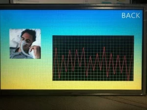
The interface is mainly used to adjust the speed, dose, and radiofrequency, so as to achieve the cosmetic effect of the face and waist.
speed adjuSTMent address 0x0001
dose regulation address 0x0002
RF regulation address 0x0003
Note:
The relationship between touch addition and subtraction and digital display box is related by variable address, so it is necessary to maintain consistency to achieve correct control.
The development of STM32L053R8

Figure 17
After selecting the corresponding chip model, click start project to enter the configuration interface.

Figure 18
Configure and select the project name and storage path, then click generate code to generate the code. After adding the protocol code, the demo can be tested. The detailed code is as follows:
Then you can download the code to the stm32 board + STONE LCD development board for testing.
Related posts:
Raspberry PI Pico and STONE Display Dazzling Light Control System
Control WS2812B_RGB Lamp by STONE Display Module
The Structure and Display Principle of High Brightness LCD
Raspberry Pi GUI using STONE HMI Touch Screen Display Module
Man-Machine Touch Demonstration of Multi Function Automobile Service Equipment
Automotive Car LCD Screen Project Solutions
Ultrasonic module test with STONE LCD module
IoT and interactive functions of HMI touch screen
By Customer : STONE Intelligent TFT Touch Display Beginners Guide
Record Medical Surgery Notes with STONE Serial LCD Screen
.jpg "STM32 Board Tutorial: Use STONE LCD Development BEAUTY DEVICES")


